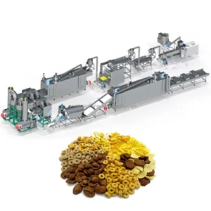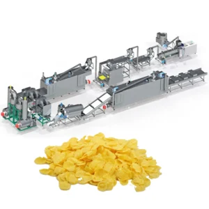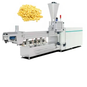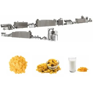
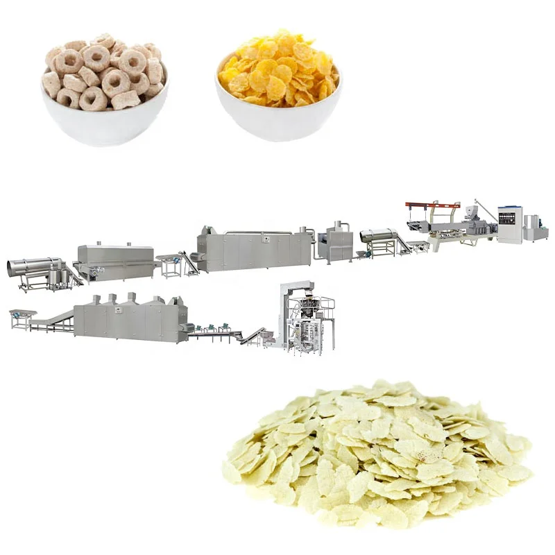
Screw and die configuration matched to the buyer’s actual cereal raw material — MT-series twin-screw extruders specify screw geometry and die profile against the confirmed corn, oat, or multi-grain blend before the barrel is assembled, so expansion behaviour and flake density align with market expectation rather than a generic build.
Technical Specifications
| Parameter | Value |
|---|---|
| Model | MT70 / MT85 / MT75 |
| Product Type | Corn Flake Extrusion Production Line |
| Screw Type | Twin-screw |
| Installed Power | 160 kW (MT70) / 190 kW (MT85) / 210 kW (MT75) |
| Power Consumption | 120 kW (MT70) / 140 kW (MT85) / 150 kW (MT75) |
| Output Capacity | 150–200 kg/h (MT70, basis not stated in source — confirm raw material / moisture) / 300–400 kg/h (MT85, basis not stated in source — confirm raw material / moisture) / 300–500 kg/h (MT75, basis not stated in source — confirm raw material / moisture) |
| Overall Dimensions (L×W×H) | 41 × 1.5 × 2.2 m (MT70) / 43 × 1.5 × 3.2 m (MT85) / 45 × 1.5 × 3.5 m (MT75) |
| Control System | PLC control at flaking station; MCC and PLC integration across full line |
| Raw Materials | Corn, rice, wheat, oat, barley powder |
| Die Configuration | Interchangeable moulds: ball, tube, stick, ring, fruit loop, star, wheel, flower, heart |
| Flaking Station | Hydraulic double-roller, dual independent motors, infrared sensor temperature control |
| Dryer Heating Source | Gas or electric |
| Roasting Oven | Vibrating pan, high-temperature spraying tubes, dual circulating fans, cyclone dust removal |
| Coating System | Double tumble sugar melting, elevator, coating drum, spraying nozzle |
| Extruder Features | Automatic lubricating and cooling; wear-resistant screw treatment |
| Standards | CE; ISO |
Application Suitability
| Application | Material or Output |
|---|---|
| Natural corn flake production | Corn powder or grits, single-grain formulation |
| Sugar-coated corn flake production | Corn, rice, or wheat base with sugar coating drum finish |
| Multi-grain breakfast cereal flakes | Blends of corn, oat, barley, wheat, and rice powder |
| Shaped cereal variants | Fruit loops, rings, stars, wheels via interchangeable die plates |
| Retail and food-service breakfast cereal | Flake thickness and blistering profile set to packaging or bulk spec |
Why Nominal Capacity Figures Mislead Cereal Buyers on Corn Flakes Extrusion Production Line Specifications
A throughput number without the raw material basis is a guess, not a guarantee.
The most common dispute after a corn flake line goes live is that the extruder cannot sustain the quoted output on the buyer’s actual formulation. Last month I ran a trial on a standard corn flour blend and the expansion looked excellent — until the client’s recipe with a significant oat proportion arrived and the flakes shattered on contact with milk. Every parameter had to be reset [NEED_CITE: raw material composition effect on extrusion expansion rate]. The corn flakes extrusion production line specifications only become meaningful when the capacity figure is tied to a specific grain blend, moisture level, and target flake density.
Barrel Temperature Profile and Starch Gelatinisation Control
Twin-screw extrusion gives the process engineer independent control over shear, residence time, and barrel temperature across multiple heating zones. For corn flake production, the degree of starch gelatinisation inside the barrel determines how the dough behaves at the die and ultimately how the flake holds its structure after roasting. The corn flakes extrusion production line specifications for the MT-series cover three capacity tiers, each with barrel zone heating and automatic lubricating and cooling to maintain thermal stability during continuous runs.
Screw Configuration as a Function of Raw Material Blend
The screw elements — conveying, kneading, and reverse sections — are assembled in a sequence that matches the specific grain formulation. A high-corn blend needs a different shear profile compared to a recipe carrying a substantial oat or barley fraction, because each starch source gelatinises at a different temperature and moisture threshold. This is where generic screw builds fail: the configuration copied from a reference product does not account for the buyer’s actual blend [NEED_CITE: twin-screw extrusion screw element arrangement principles]. Die design works in tandem with screw geometry to set the dough pressure and expansion rate at the exit point.
Reading the Parameter Sheet Beyond Installed Power
The installed power and power consumption figures across the MT70, MT85, and MT75 models reflect the total connected load including extruder drive, barrel heaters, and auxiliary systems. Power consumption represents typical operating draw under standard conditions. The hydraulic double-roller flaking station uses dual independent motors, which allows each roller to be driven separately — this matters when the dough sheet thickness needs fine adjustment without altering roller gap mechanically. Infrared sensor temperature control on the flaking station keeps the dough sheet at a consistent plasticity entering the rollers, which directly affects final flake thickness uniformity. The roasting oven uses a vibrating pan with high-temperature spraying tubes and dual circulating fans, so blistering occurs evenly across the flake surface rather than concentrating at the edges where airflow is typically stronger.
What Happens When Stations Are Not Throughput-Matched
An extruder that outpaces the dryer creates a backlog of wet flakes that mat together before moisture is removed. A roasting oven that cannot keep up with the flaking station forces the operator to reduce line speed, meaning the extruder runs below its designed capacity and the screw fill ratio drops — which in turn changes shear and gelatinisation behaviour. These mismatches are invisible on a specification sheet that lists each machine in isolation [NEED_CITE: production line throughput balancing between extrusion and downstream stations]. The bottleneck only reveals itself during commissioning, when the buyer discovers the line cannot sustain the expected output without product quality drifting outside specification.
Procurement Verification from a Process Engineering Perspective
The MT-series lines are supplied with screw configuration and die design specified to the buyer’s confirmed raw material blend, not selected from a catalogue of generic builds. Throughput matching across the extruder, flaking station, dryer, roasting oven, and coating drum is calculated during the layout phase so each station handles the upstream output without bottlenecking. The in-house testing workshop runs the buyer’s actual raw material before shipment, producing a trial run report that documents expansion behaviour, flake density, and process parameters — so recipe adjustments happen in the factory, not on the buyer’s floor during commissioning. Electrical schematics with voltage and frequency confirmation are reviewed before production begins, avoiding the situation where a control cabinet arrives wired for a supply standard that does not match the facility. The PLC and MCC control integration across the full line allows recipe parameters to be saved and recalled, supporting batch-to-batch consistency once production is established.
Documentation & Verification
- Line layout and capacity calculation showing throughput balance across every station
- Screw and die configuration record tied to your confirmed grain blend and target flake density
- Trial run report on your actual raw material from the in-house testing workshop
- Electrical schematic with voltage and frequency matched to your facility specification
- CE declaration of conformity and ISO certificate for import and compliance documentation
- Operation and maintenance manual with wear parts list for screws, dies, and roller surfaces
Installation, Commissioning & Support
- Line footprint of 41–45 m length requires level concrete flooring with drainage at dryer and roasting stations
- Power supply must support 160–210 kW installed load with dedicated circuit breaker per station
- Flaking station and roasting oven ship partially assembled; on-site mechanical alignment included
- First-run commissioning covers screw speed, barrel temperature profile, and roller gap setting to your recipe
- Operator training addresses PLC parameter recall, die changeover, and roller surface inspection
- Wear parts list covers screws, die plates, and flaking roller shells with recommended replacement intervals
What to Prepare Before Requesting a Line Quotation
To move from an initial inquiry to a meaningful corn flakes extrusion production line specifications proposal, the useful starting information includes the grain formulation and any secondary ingredients, the target flake thickness and density, and the intended daily or shift-based production volume. The facility supply voltage and frequency, along with the preferred control language for the PLC interface, should be confirmed early to avoid rework during production. If the line must integrate with an existing mixing system or packing station, providing the interface point details allows the layout to account for throughput matching at those boundaries.
Frequently Asked Questions
Q: How is the extruder capacity verified against my specific cereal formulation and moisture content?
A: The buyer sends the actual raw material blend to the in-house testing workshop, where a trial run documents expansion rate, dough behaviour at the die, and flake density on the hydraulic roller station. The resulting report becomes the baseline for screw configuration and process parameters before the production line is assembled.
Q: Which screw configuration and die design suit a multi-grain flake recipe versus pure corn?
A: Screw element arrangement — the sequence of conveying, kneading, and reverse sections — changes with each grain blend because oat, barley, and wheat starches gelatinise differently from corn. Die geometry is matched to the dough viscosity at the exit point, which shifts as the formulation changes, so each recipe receives its own configuration record.
Q: How are voltage, frequency, and control language confirmed before production begins?
A: The electrical schematic and voltage confirmation document is reviewed with the buyer during the specification phase, before any cabinet wiring starts. The PLC interface language is set at this stage so operators see their working language on commissioning day, avoiding delays caused by relabelling or reprogramming on site.
Q: What documentation accompanies the line from design through to shipment?
A: The documentation package includes the line layout and capacity calculation, screw and die configuration record, electrical schematic, trial run report on the buyer’s raw material, CE declaration of conformity, ISO certificate, factory test record, operation and maintenance manual, wear parts list, and packing photographs with customs documentation support.
Q: How is throughput balanced across extruder, flaking, drying, roasting, and coating to prevent bottlenecks?
A: Each station’s capacity is calculated against the extruder output during the layout phase, so the dryer, roasting oven, and coating drum all handle the upstream flow without accumulating product. This matching is documented in the line layout and verified during the factory trial run before dispatch.