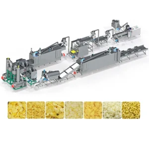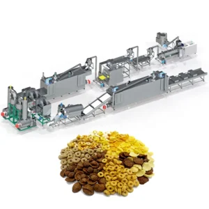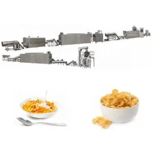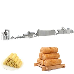
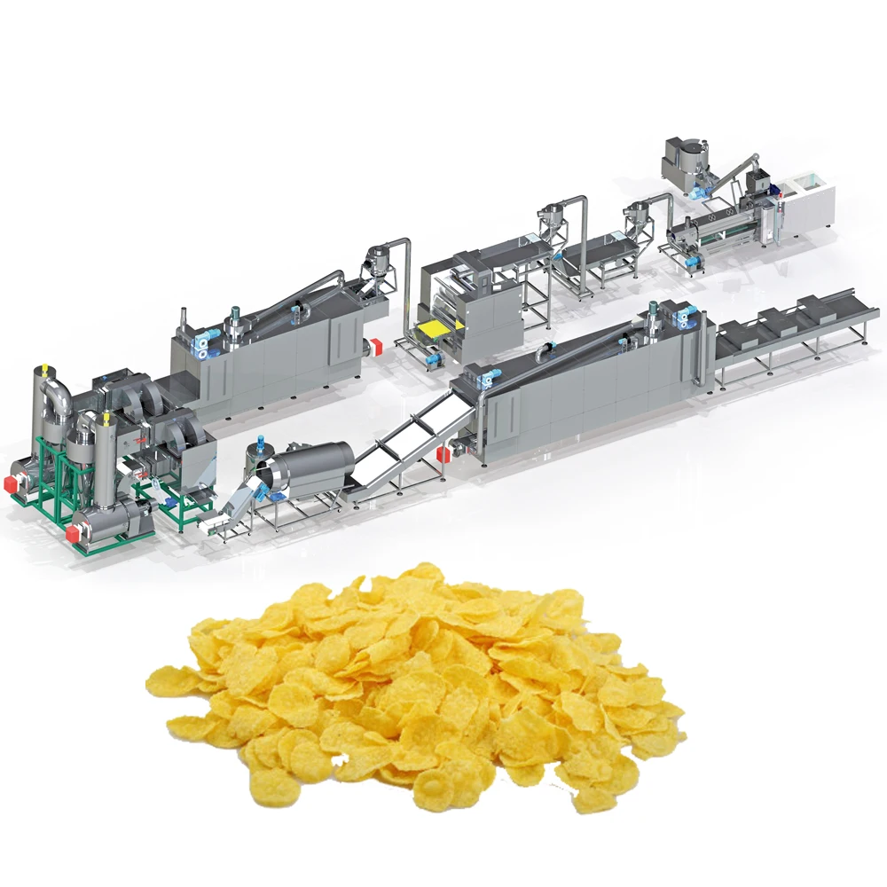
Screw Configuration Matched to Your Formula — Every corn flake extrusion run begins with adjusting the screw elements and die geometry to the exact grain blend and moisture level you use in production.
Technical Specifications
| Parameter | Value |
|---|---|
| Product Type | Corn Flakes Production Line |
| Model Options | MT70 / MT85 / MT75 |
| Screw Type | Twin Screw |
| Installed Power (MT70 / MT85 / MT75) | 160 kW / 190 kW / 210 kW |
| Power Consumption (MT70 / MT85 / MT75) | 120 kW / 140 kW / 150 kW |
| Output Capacity (MT70 / MT85 / MT75) | 150–200 kg/h (basis not stated in source — confirm raw material type and moisture content) / 300–400 kg/h (basis not stated in source) / 300–500 kg/h (basis not stated in source) |
| Overall Dimensions (MT70 / MT85 / MT75) | 41 × 1.5 × 2.2 m / 43 × 1.5 × 3.2 m / 45 × 1.5 × 3.5 m |
| Flaking Machinery | Hydraulic double-roller system, separate motor driving, infrared sensor temperature control |
| Control System | PLC (flaking station), MCC (complete line integration) |
| Dryer Heating Source | Gas / Electric |
| Hot Air Roasting Oven | Vibrating pan, high-temperature spraying tubes, reconciliation burner, dual circulating fans, cyclone dust removal |
| Coating System | Double tumble sugar melting, elevator, coating drum, spraying nozzle |
| Extruder Features | Automatic lubricating, cooling function, wear-resistant screw elements |
| Voltage & Frequency | Configurable to target market electrical standard (basis to be confirmed) |
| Certifications | CE, ISO |
Application Suitability
| Application | Material or Output |
|---|---|
| Natural corn flakes | Corn grits, corn flour blends |
| Sugar-coated corn flakes | Corn, rice, wheat base with sugar syrup coating |
| Multi-grain breakfast flakes | Oat, barley, wheat, rice powder blends |
| Puffed snack shapes (alternative die) | Ball, tube, stick, ring, fruit loop, star, wheel, flower, heart |
Why Generic Screw Builds Produce the Wrong Flake Density
A corn flakes extrusion production line screw configuration die design copied from a standard template ignores what actually happens inside the barrel when your specific grain blend meets heat and shear.
I have stood next to a flaking roller watching extruded pellets come out too dense to press into a thin, crisp flake. The line was rated for a certain throughput, but the buyer was running a high-fiber oat and barley mix instead of straight corn grits. The screw elements were set for low-shear gelatinisation, so the starch never fully opened up. The pellets hit the roller and cracked instead of flattening. That mismatch does not show up in a brochure — it only shows up on the factory floor when the bowl-life test fails and the flakes turn soggy in under two minutes [NEED_CITE: starch gelatinisation thresholds in multi-grain extrusion].
How Shear and Residence Time Shape the Pellet
The twin-screw extruder processes grain through a sequence of feeding, mixing, shearing, and cooking zones. Screw element arrangement — the ratio of kneading blocks to conveying elements — determines how much mechanical energy transfers into the dough. A higher proportion of kneading blocks increases shear, which is necessary for corn grits with a hard endosperm but excessive for delicate oat flour. The corn flakes extrusion production line screw configuration die design must account for the particle size distribution of the incoming meal, because coarse grits require longer residence time in the cooking zone to reach full gelatinisation before the die.
Barrel Temperature Profile and Starch Gelatinisation
Barrel heating zones work in sequence to bring the dough from ambient to the gelatinisation window gradually. If zone two spikes too early, surface moisture flashes off and the remaining core stays raw, producing a pellet with a hard center that the flaking roller cannot compress evenly. Each zone must be tuned to the thermal conductivity of the grain blend. High-fat formulations conduct heat differently than lean corn meal, and the reconciliation burner in the roasting oven downstream can only develop surface blistering if the pellet core moisture is already within a narrow band [NEED_CITE: thermal conductivity differences in high-fiber cereal blends].
Reading the Specifications Against Your Process
Installed power across the MT70, MT85, and MT75 models ranges from 160 kW to 210 kW, reflecting different barrel volumes and motor ratings. The gap between installed and consumed power — roughly 40–60 kW across models — represents the thermal and mechanical headroom available when the extruder encounters a viscous, high-moisture dough. The flaking station uses hydraulic pressure on double rollers driven by separate motors, which prevents slippage when the pellet sheet is thin. Infrared sensors on the roller surface maintain consistent temperature so the flake does not stick or tear during compression.
The Cost of Skipping the Trial Run
When a line ships without a trial run on the buyer’s actual raw material, commissioning becomes the first real test. Engineers adjust screw elements on-site, burning through raw material and production time to find the correct configuration. Flaking rollers may need re-shimming if the pellet density is outside the expected range. Voltage mismatches can delay start-up entirely if the control cabinet was wired for a different market’s frequency standard. These are not catastrophic failures — they are preventable delays that push back the first commercial shipment by weeks [NEED_CITE: commissioning delays in extrusion line installations].
Why Engineers Specify Here
The in-house testing workshop runs your grain blend through the extruder before the line ships, generating a trial report that records the working screw configuration and die design. Throughput is matched across every station — extruder, flaking roller, dryer, and roasting oven — so one segment does not bottleneck the next. The PLC and MCC control architecture keeps flaking parameters locked in once they are established during the trial. CE and ISO compliance documentation accompanies each shipment, and electrical schematics confirm voltage and frequency before the cabinet is built.
Documentation & Verification
- Screw and die configuration record tied to your specific grain blend and target flake density
- Trial run report from in-house testing workshop using your supplied raw material
- Line layout drawing with throughput calculations for every station from mixer to packer
- Electrical schematic confirming voltage, frequency, and control language for your facility
- Factory test record documenting barrel temperature profile and flaking roller gap settings
Installation, Commissioning & Support
- Foundation layout accounts for the 41–45 m line footprint and vibrating pan load in the roasting oven
- Dedicated power circuit sized to the MT model’s installed power draw, with isolation for the MCC cabinet
- Flaking station hydraulic system calibrated on-site to match pellet density from the trial run
- PLC interface language and alarm labels set to operator preference before first production run
- Wear parts list covers screw elements, die plates, and roller surfaces with recommended replacement intervals
- Annual maintenance schedule aligned to lubrication system service and infrared sensor recalibration
What to Prepare Before Requesting a Quote
Share your grain formulation — including the percentage of corn, oat, barley, or rice in the blend — along with the particle size distribution of the milled meal. Specify whether you are targeting natural flakes, sugar-coated flakes, or both, as the coating drum and sugar melting system change the line layout. Confirm your facility’s voltage and frequency standard so the MCC panel is built to match.
Frequently Asked Questions
Q: How is the screw configuration matched to my grain blend before shipment?
A: We run your supplied raw material in the in-house testing workshop, adjusting kneading block ratio, conveying element pitch, and die geometry until the pellet achieves the gelatinisation level and density your flaking roller requires. The working configuration is recorded and shipped with the line.
Q: What does the trial run report cover?
A: The report documents barrel temperature settings across all zones, screw element arrangement, die opening, moisture content at the extruder exit, pellet density, and flaking roller gap. It serves as the baseline parameter set for your first production run on-site.
Q: How is throughput balanced between the extruder and downstream stations?
A: Each station — flaking roller, dryer, and hot air roasting oven — is sized so its processing rate matches the extruder output. The layout calculation confirms that no single segment creates a bottleneck, preventing pellet backlog or dryer overload during continuous operation.
Q: What electrical details need confirming before the control panel is built?
A: Voltage, frequency, and phase configuration must match your facility supply. The MCC cabinet wiring and PLC component ratings are set accordingly. Control language for the HMI interface is also confirmed at this stage to avoid rework during commissioning.
Q: Can the same line produce both natural and sugar-coated flakes?
A: Yes. The base extrusion and flaking stations remain the same. A sugar melting system, coating drum, and additional drying segment are added downstream for coated product. The line layout accounts for both configurations during the design phase.