Precision-matched screw geometry — barrel zones and die land length configured to your specific grain blend and moisture content, verified on your raw material before dispatch.
Technical Specifications
| Parameter | Value |
|---|---|
| Product Type | Corn Flakes Extrusion Production Line |
| Model | MT75 / MT70 / MT85 |
| Screw Type | Twin Screw |
| Installed Power | MT70: 160 kW; MT75: 210 kW; MT85: 190 kW |
| Power Consumption | MT70: 120 kW; MT75: 150 kW; MT85: 140 kW |
| Output Capacity | MT70: 150–200 kg/h; MT75: 300–500 kg/h; MT85: 300–400 kg/h (basis to be confirmed) |
| Overall Dimensions (L×W×H) | MT70: 41 × 1.5 × 2.2 m; MT75: 45 × 1.5 × 3.5 m; MT85: 43 × 1.5 × 3.2 m |
| Control System | PLC and MCC integrated automation |
| Flaking Station | Hydraulic double-roller system, independent dual motors, infrared temperature sensing |
| Dryer Heating Source | Gas or Electric (configurable) |
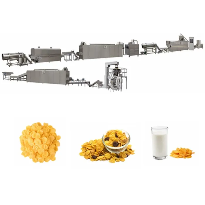
| Roasting Oven | Hot air circulation with vibrating pan, high-temperature spray tubes, dual circulating fans, cyclone dust removal |
| Coating System | Double tumble drum with sugar melting, elevator, spray nozzle array |
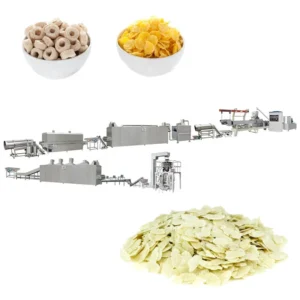
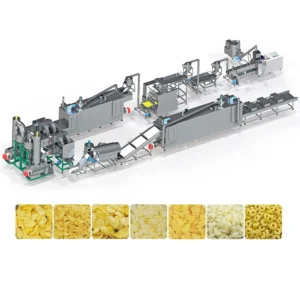
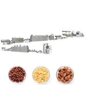
| Line Configuration | Mixing → Extruding → Flaking → Drying → Hot Air Roasting → Sugar Coating (optional) → Secondary Drying → Cooling → Packing |
| Basic Raw Materials | Corn, rice, wheat, oat, barley powder |
| Final Product Formats | Natural corn flakes, sugar-coated flakes, multiple extruded shapes (ball, tube, ring, star, flower, heart) |
| Assembly State | Complete integrated line |
| Automation Level | Fully automatic |
| Certification | CE, ISO |
Application Suitability
| Application | Material or Output |
|---|---|
| Natural corn flakes for breakfast cereal packaging | Corn grits and corn flour blends |
| Sugar-coated and honey-glazed corn flakes | Corn base with sucrose, maltose, or honey spray coating |
| Multi-grain breakfast flakes | Rice, wheat, oat, and barley powder combinations |
| Extruded cereal snack shapes | Corn and rice blends formed into rings, stars, tubes, and fruit loops |
| Fortified nutritional flakes for institutional feeding programmes | Grain base with added vitamin and mineral premix |
Why Nominal Capacity Figures Mislead Breakfast Cereal Buyers
A corn flakes extrusion production line quoted at a fixed hourly output rarely accounts for how your specific grain formulation behaves inside the barrel.
I have watched lines arrive on site, get bolted down, and then fail to hold their stated throughput the moment local corn grits replaced the supplier’s test material. The extruder runs, but the flakes come out dense, under-expanded, or too thick to toast properly. The bottleneck is never the motor — it is the screw configuration and die geometry that were never matched to the buyer’s actual starch composition and particle size [NEED_CITE: starch gelatinisation behaviour across different corn varieties]. When the extrusion parameters are wrong, every downstream station — the flaker, the dryer, the roaster — operates outside its design envelope, compounding the loss across the entire shift.
Barrel Temperature Profile and Starch Gelatinisation Control
The corn flakes extrusion production line relies on precise thermal staging along the barrel to achieve full starch gelatinisation without premature expansion. Multiple independent heating zones allow the operator to build a gradual temperature ramp, ensuring the corn dough reaches the correct viscosity before it exits the die. If the profile is too aggressive, the melt fractures; too conservative, and the gelatinisation remains incomplete, producing flakes that shatter during roasting rather than developing the characteristic surface blister.
Die Land Length and Flake Density Behaviour
Die design directly governs how the extrudate expands upon exiting the barrel. The land length — the straight section of the die channel — controls back-pressure and therefore the density of the extruded rope. For corn flakes, the target is a semi-expanded pellet that the flaking rollers can compress into a uniform sheet without cracking. A die specified for puffed snacks will produce material too airy to flake; a die for dense pellets will overload the hydraulic rollers and cause inconsistent thickness across the sheet width [NEED_CITE: die geometry influence on extrudate density in twin-screw systems].
Reading the Power and Dimension Data Correctly
The three available models — MT70, MT75, and MT85 — differ in installed power, physical footprint, and throughput envelope. Installed power ranges from 160 kW on the MT70 to 210 kW on the MT75, while actual power consumption sits notably lower, between 120 kW and 150 kW. This gap reflects the thermal and mechanical headroom built into the main drive, allowing the screw to handle viscous, high-starch dough without stalling during start-up transients. The line lengths span 41 m to 45 m, which directly affects factory floor planning — the roasting oven and secondary dryer together occupy considerable linear space, and the cyclone dust removal unit requires clearance above the hot air roaster. The hydraulic flaking station uses dual independent motors for each roller, meaning roller speed can be adjusted differentially to control sheet tension before the material enters the dryer.
The Hidden Cost of Generic Screw Configurations
When a supplier copies a screw and die build from a standard catalogue rather than specifying it to your grain blend, the consequences surface slowly. The line runs, but flake thickness drifts outside tolerance. The roaster must work harder to achieve surface colour, driving up gas consumption. Sugar coating adhesion becomes uneven because the flake surface texture is wrong [NEED_CITE: relationship between extrudate surface porosity and coating adhesion]. Operators compensate by slowing the line, which means the quoted capacity was never real in the first place. I have seen buyers spend months adjusting dryer temperatures and roller gaps trying to fix a problem that originated in the screw element sequence.
Why Procurement Decisions Land Here
Screw configuration and die design are specified to your raw material formulation and target flake density, not pulled from a generic build library.
The in-house testing workshop runs your actual grain blend through the extruder before shipment, generating a trial report that documents barrel temperatures, screw speed, moisture levels, and flake dimensions under real conditions.
Throughput is calculated across every station — extruder, flaker, dryer, roaster, coater — so no single unit bottlenecks the corn flakes extrusion production line during continuous operation.
PLC and MCC control is integrated from batching through packing, with the control language and interface configured to your operator team before the panels leave the factory.
Pre-sales engineering covers line layout, utility planning, and phased installation scheduling, reducing on-site commissioning time once the equipment arrives.
Documentation & Verification
- Line layout drawing showing throughput balance across all stations from mixer to packer
- Screw and die configuration record matched to your grain formula and target flake density
- Trial run report on your raw material documenting extrusion parameters and flake quality metrics
- Electrical schematic with confirmed voltage, frequency, and control language for your facility
- CE declaration of conformity and ISO certificate for customs and regulatory submission
- Operation and maintenance manual with wear parts list specific to your screw element sequence
Installation, Commissioning & Support
- Foundation plan accounting for the 41–45 m line length and hydraulic flaker point loads
- Dedicated power circuit sized to the MT75 210 kW installed load with voltage and frequency confirmed for your grid
- Equipment ships in modular sections; on-site assembly follows a sequenced schedule from extruder through roaster
- First production run supervised by commissioning engineer who sets barrel zone temperatures and roller gap to trial report values
- Operator training covers PLC interface navigation, screw speed adjustment, and flaker hydraulic pressure tuning
- Wear parts inventory includes spare screw elements, die inserts, and flaker roller surfaces matched to your configuration
What to Include in Your Inquiry
To configure a corn flakes extrusion production line that holds its throughput on your material, share your grain formulation and particle size distribution, target daily output in finished flake weight, and your facility’s available floor length and ceiling height. Specify local voltage and frequency so the MCC and motor drives are wound correctly before production begins. If you plan to run multiple grain blends — corn, multi-grain, oat-based — list each one so the screw configuration can accommodate the full range.
Frequently Asked Questions
Q: How is screw configuration matched to my grain blend and target flake density?
A: The screw element sequence — conveying, kneading, and reverse elements — is arranged based on your grain’s starch content, particle size, and the flake density your market expects. The die land length is then calculated to produce the correct back-pressure for consistent extrudate density entering the flaker. Every configuration is documented and reproducible for future orders.
Q: Can I run a trial on my raw material before shipment?
A: Yes. The in-house testing workshop runs your actual grain blend through the extruder and downstream stations. The trial report records barrel temperature profile, screw speed, moisture addition rate, flake thickness, and surface quality. This data transfers directly to your line during commissioning, eliminating weeks of on-site recipe development.
Q: How are voltage, frequency, and control language confirmed for my facility?
A: During the specification phase, your local grid data is collected and cross-referenced with motor nameplate requirements. The MCC is wired and the PLC interface is loaded with your preferred language before factory testing. Electrical schematics are included in the documentation package for your local electrician’s reference.
Q: What barrel temperature profile is used for consistent starch gelatinisation?
A: The profile is staged across multiple independent heating zones, typically ramping from the feed section through the gelatinisation zone to the metering zone near the die. Exact setpoints depend on your grain formulation and moisture content, and are established during the trial run on your material rather than assumed from generic recipes.
Q: How is throughput balanced between extruder, flaker, dryer, and roaster?
A: Each station is sized during the line layout phase based on your target output and the residence time each process requires. The flaker roller width, dryer belt length, and roaster pan area are all calculated so that no station forces the upstream extruder to run below its optimal screw speed or the downstream units to accumulate buffer stock.