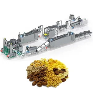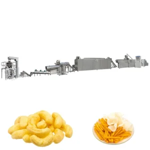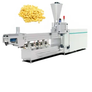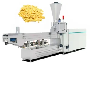
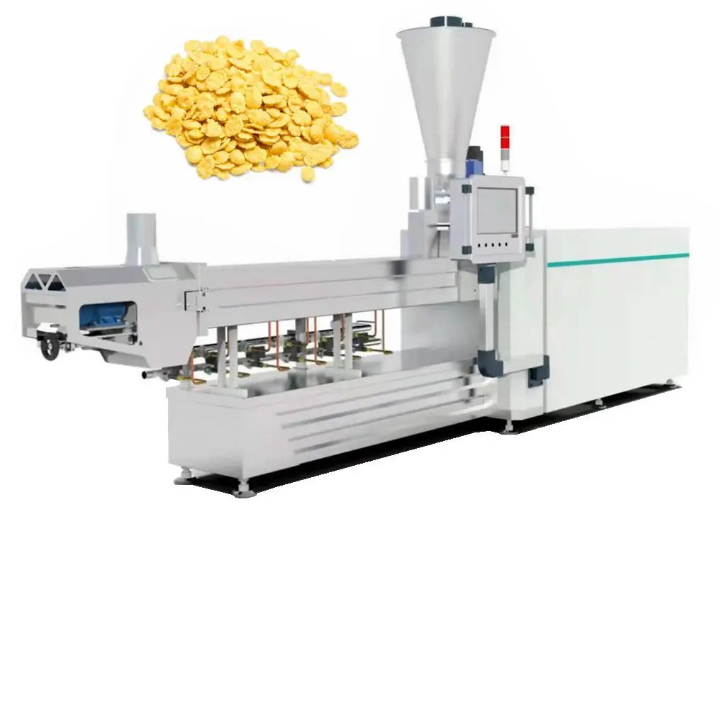
Screw and Die Configured to Recipe — Every MT-65, MT-70, MT-75 and MT-85 corn flakes extrusion line ships with screw elements and die geometry selected against the buyer’s actual grain blend, verified in an on-site testing workshop before dispatch.
Technical Specifications
| Parameter | Value |
|---|---|
| Product Type | Corn Flakes Production Line |
| Line Models | MT-65 / MT-70 / MT-75 / MT-85 |
| Extruder Type | Twin-screw |
| MT-65 Installed Power | 84 kW (real power 59 kW) |
| MT-65 Output | 120–150 kg/h (basis not stated in source — confirm raw material, moisture and product format) |
| MT-65 Dimensions | 21,000 × 1,200 × 2,200 mm |
| MT-70 Installed Power | 132 kW (real power 92 kW) |
| MT-70 Output | 200–250 kg/h (basis not stated in source — confirm raw material, moisture and product format) |
| MT-70 Dimensions | 23,000 × 1,500 × 2,200 mm |
| MT-75 Installed Power | 186 kW (real power 140 kW) |
| MT-75 Output | 400–500 kg/h (basis not stated in source — confirm raw material, moisture and product format) |
| MT-75 Dimensions | 24,000 × 1,500 × 2,800 mm |
| MT-85 Installed Power | 239 kW (real power 167 kW) |
| MT-85 Output | 300–400 kg/h (basis not stated in source — confirm raw material, moisture and product format) |
| MT-85 Dimensions | 28,000 × 3,500 × 4,300 mm |
| Flaking Roller Material | Cast iron with water cooling; shaft 45# steel, frame carbon steel |
| Hot Air Roaster Max Temp | Up to 400 °C |
| Roaster Heating Source | Electric or gas |
| Dryer Layers | Three, five or seven available |
| Dryer Heating Source | Electric or gas |
| Sugar Spraying System Power | 28.75 kW |
| Sugar Spraying Dimension | 4,000 × 1,900 × 1,880 mm |
| Packing Machine Models | 420 / 520 / 620 / 720 |
| Control System | Button start, real-time monitoring, data storage, alarm functions |
| Extruder Design Method | 3D software design with analogue simulation and computer automatic testing |
| Certifications | CE (since 2014), ISO certified |
Application Suitability
| Application | Material or Output |
|---|---|
| Classic corn flakes | Corn grits, plain or sugar-coated |
| Multi-grain breakfast flakes | Rice, millet, wheat, oat and barley powder or grits |
| Puffed cereal rings | Corn and oat blends formed into Cheerios-type shapes |
| Cocoa and honey loops | Flavoured cereal dough with cocoa powder or honey glaze |
| Corn balls and star shapes | Extruded and puffed corn-based formats |
| Fortified cereal flakes | Grain blends with added vitamin and mineral premix |
| Oatmeal flake processing | Dehulled oat groats pressed into flat flakes |
Why "Rated Capacity" Misleads Breakfast Cereal Buyers
A line rated at a nominal throughput on paper often delivers less on the grain blend the buyer actually uses.
Capacity figures quoted in a brochure rarely state the moisture content, grain particle size or recipe behind them. When a corn flakes extrusion line is sized only by extruder barrel diameter and motor power, the downstream stations — flaking, drying, roasting — may not keep pace on a denser or wetter dough. The result is a bottleneck that surfaces only after installation, when raw material costs are already committed and production schedules slip [NEED_CITE: throughput matching between extrusion and downstream stations in cereal processing]. Buyers who specify a line on a single output number without requiring a trial run on their own corn grits or multi-grain recipe absorb that risk entirely.
Barrel Sections and Temperature Zones Shape Flake Texture
The twin-screw extruder in this corn flakes extrusion production line turnkey configuration uses independently controlled barrel heating zones. Starch gelatinisation in corn grits requires a precise temperature ramp — too low and the dough remains granular, producing brittle flakes that shatter during roasting; too high and the starch degrades, leaving a gummy centre. Screw element sequencing determines shear intensity and residence time, which together govern how completely the starch converts. Meiteng configures the screw profile and die aperture to the specific grain and moisture level the buyer supplies, rather than applying a generic build.
Die Geometry Determines Expansion and Flake Density
The die plate at the extruder outlet controls pellet shape, diameter and length before the dough reaches the flaking rollers. A die with too many orifices for a given throughput produces thin, under-expanded pellets that roast unevenly; too few orifices force excessive back-pressure and drive up motor load. For a corn flakes extrusion production line turnkey project targeting consistent bowl density — the measure consumers judge when the flake meets milk — the die pattern must match both the extruder output rate and the downstream roaster’s thermal capacity [NEED_CITE: breakfast cereal bowl density standards and consumer expectation]. This is why die selection happens after the raw material trial, not before.
How Roller Gap and Roaster Temperature Interact
The flaking machine uses water-cooled cast iron rollers with an adjustable gap to press extruded pellets into uniform flakes. Thinner gaps produce crisp flakes but increase the risk of breakage during conveying and packing. The hot air roaster, operating up to 400 °C with a high-pressure blower, then puffs each flake to its final volume and colour. If the roller gap is set without accounting for the roaster’s heat transfer rate, flakes can scorch on the surface while remaining soft inside. The three stations — extruder, flaker, roaster — must be tuned as one system, which is achievable only when a single supplier controls all three and validates the setting during pre-shipment testing.
The Cost of Mismatched Stations Down the Line
An extruder running at full output while the dryer falls behind forces operators to slow the entire line or divert wet flakes to waste. A sugar spraying drum sized below the packing machine’s feed rate leaves the packer idle between batches. These imbalances do not show up in a spec sheet that lists only extruder capacity. Buyers who assemble stations from separate vendors discover the mismatch during commissioning, when re-engineering a conveyor height or swapping a dryer mesh belt means weeks of lost production [NEED_CITE: cereal line commissioning delays from throughput mismatch]. Specifying the full sequence under one supplier removes that gap.
Why Buyers Source This Line From Meiteng
The in-house testing workshop runs the buyer’s exact corn grits or oat blend through the configured screw and die before the line ships, producing a trial run report that records real throughput, flake thickness and moisture loss. Screw and die configuration records are kept on file so replacements match the original geometry exactly. Line layout drawings show throughput calculations at every station, not just the extruder, so the dryer, roaster and packing machine are demonstrably matched. Electrical schematics confirm voltage, frequency and control language before metal is cut, preventing commissioning delays at the buyer’s facility. Wear parts lists ship with the first order, ensuring screws, dies and roller surfaces are available when the first replacement falls due.
Documentation & Verification
- Line layout with station-by-station throughput calculation for the chosen model
- Screw and die configuration record matched to buyer’s grain recipe
- Trial run report on customer-supplied raw material before dispatch
- Electrical schematic confirming voltage, frequency and control language
- CE declaration of conformity and ISO certificate copies
- Wear parts list with original screw element and die geometry codes
Installation, Commissioning & Support
- Foundation plan accounts for MT-85 footprint up to 28 m and vibration load from the flaking rollers
- Power supply sized to installed capacity with dedicated circuit for the roaster’s heating elements
- On-site assembly supervised through first run, including flaker gap calibration
- Operator training covers screw element swap procedure and die changeover
- Spare screw elements and replacement die plates supplied with initial order
- Periodic maintenance schedule covers roller bearing inspection and mesh belt tensioning
What to Share With Your Inquiry
Provide the grain type, particle size and target moisture content so the screw configuration can be drafted before quotation. State the daily output target and the number of operating shifts to guide model selection between the MT-65 and MT-85. Confirm the local voltage, frequency and the preferred control panel language so the electrical design is finalised before production starts.
Frequently Asked Questions
Q: How is line capacity verified on my specific raw material and recipe before the equipment ships?
A: The buyer sends a representative batch of their actual corn grits or grain blend to the in-house testing workshop. The configured extruder, flaker and roaster run the material, and a trial run report records real throughput, flake thickness, moisture loss and colour. The line ships only after the buyer reviews and approves these results.
Q: How are screw configuration and die design chosen for my target flake thickness and density?
A: Screw element sequencing and die orifice pattern are selected based on the grain type, moisture content and target bowl density. The configuration is tested during the pre-shipment trial run. A configuration record is retained so that future replacement screw sets and dies match the validated geometry exactly.
Q: What voltage, frequency and control language options are confirmed before production?
A: The buyer’s local supply voltage, frequency and phase are confirmed during the specification stage. Control panel labels and HMI language are set to the buyer’s preference before the electrical cabinet is wired, preventing delays at commissioning.
Q: How is throughput matched between the extruder, flaking machine, roaster, dryer and packing station?
A: Each station’s capacity is calculated from the extruder’s verified output on the buyer’s recipe. The line layout document shows the rated throughput at every station, so the dryer belt speed, roaster residence time and packing machine feed rate are all sized to prevent bottlenecks.
Q: What spare wear parts are included and how are replacements supplied?
A: A wear parts list accompanies the first shipment, covering screw elements, die plates and flaking roller surfaces. Replacement parts are manufactured to the original configuration record and can be shipped on short lead times to minimise unplanned downtime.