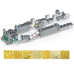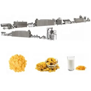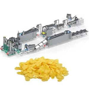
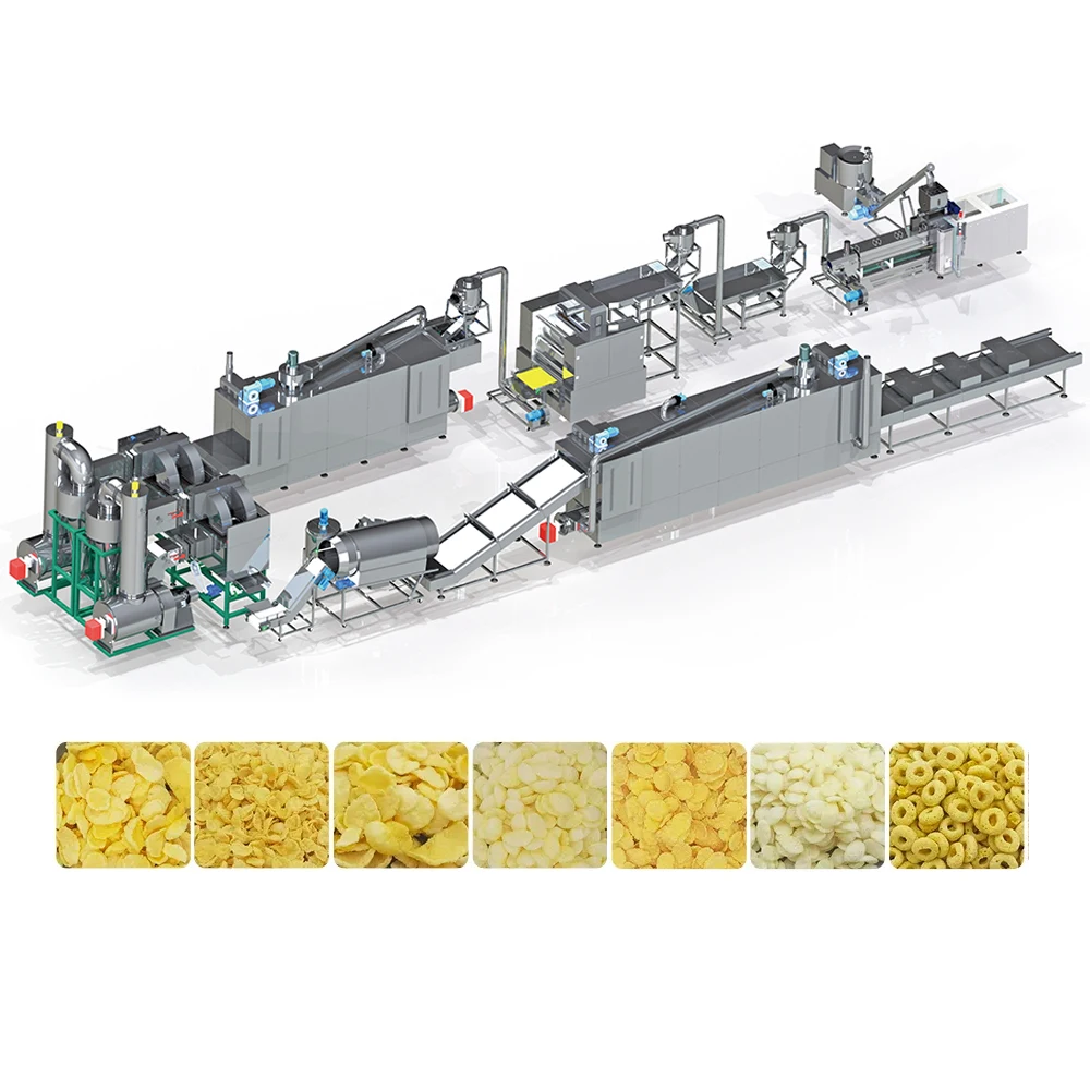
Screw Geometry Matched to Grain Formulation — MT70 / MT85 / MT75 lines specify screw elements and die bore to your corn, wheat or oat recipe rather than copying a generic twin-screw build.
Technical Specifications
| Parameter | Value |
|---|---|
| Product Type | Twin Screw Extrusion Corn Flakes Production Line |
| Model Options | MT70 / MT85 / MT75 |
| Screw Configuration | Twin Screw, wear-resistant elements |
| Installed Power (MT70) | 160 kW |
| Installed Power (MT85) | 190 kW |
| Installed Power (MT75) | 210 kW |
| Power Consumption (MT70) | 120 kW |
| Power Consumption (MT85) | 140 kW |
| Power Consumption (MT75) | 150 kW |
| Output Capacity (MT70) | 150-200 kg/h (basis to be confirmed) |
| Output Capacity (MT85) | 300-400 kg/h (basis to be confirmed) |
| Output Capacity (MT75) | 300-500 kg/h (basis to be confirmed) |
| Overall Dimensions (MT70) | 41 × 1.5 × 2.2 m |
| Overall Dimensions (MT85) | 43 × 1.5 × 3.2 m |
| Overall Dimensions (MT75) | 45 × 1.5 × 3.5 m |
| Control System | PLC and MCC |
| Flaking Roller Drive | Double motors, separate drive |
| Flaking Roller Pressure | Hydraulic system |
| Flaking Temperature Control | Infrared sensor, even temperature pipe |
| Dryer Heating Source | Gas or Electric |
| Roasting Oven | Hot air, conciliation burner, dual circulating fans, cyclone dust removal |
| Coating System | Double tumble sugar melting, elevator, coating drum, spray nozzle |
| Line Stations | Mixing → Extruding → Flaking → Drying → Hot Air Roasting → Sugar Spraying & Coating → Drying → Cooling → Packing |
| Final Product Variants | Natural corn flakes, sugar-coated flakes, shaped cereals (ball, tube, stick, ring, fruit loop, star, wheel, flower, heart) |
| Raw Materials | Corn, rice, wheat, oat, barley powder |
| Extruder Lubrication | Automatic lubricating and cooling |
| Standards | CE (since 2014), ISO |
Application Suitability
| Application | Material or Output |
|---|---|
| Natural corn flakes for breakfast cereal market | Corn grits and corn flour, whole-grain or degerminated |
| Sugar-coated and honey-glazed flakes | Corn base with post-roast sugar tumble coating |
| Multi-grain breakfast cereals | Blends of rice, wheat, oat and barley powder |
| Shaped cereal formats (rings, balls, stars) | Same extrusion platform with adjusted die plate |
| Fortified nutrition programme cereals | Grain blends with added vitamin and mineral premix |
What Your Corn Formula Has to Do With Screw Pitch
A corn flakes extrusion production line screw configuration only holds rated output when element geometry matches the starch behaviour of your specific grain mix.
I have stood beside a flaking line that ran fine on the supplier’s test corn, then choked within hours once the buyer switched to a whole-wheat pre-mix with higher fibre content. The die bore was sized for pure corn starch gelatinisation, and the extra fibre changed melt viscosity enough to cause back-pressure and repeated shutdowns [NEED_CITE: starch gelatinisation temperature variance across grain types]. Every restart meant cooling the barrel, clearing the die and losing the first batch of flakes to uneven thickness. That line eventually ran, but only after the screw profile and die plate were re-specified for the buyer’s actual recipe. This is why a corn flakes extrusion production line screw configuration conversation has to happen before the quotation, not after installation.
Barrel Temperature Zones and Starch Conversion
The barrel is divided into multiple heating and cooling zones, each governed by the PLC. A corn flakes extrusion production line screw configuration must balance shear heat from the screw elements with external barrel heat so that starch gelatinises fully before the melt reaches the die. Too little conversion and the flakes crack during roasting; too much and the dough becomes sticky on the flaking rollers.
Die Bore Diameter Versus Flake Density
Die bore determines the strand diameter entering the flaking gap. Natural corn flakes need a strand that compresses into a thin, blister-prone sheet, while sugar-coated variants benefit from a slightly denser pellet that survives the coating drum without breaking. The die is therefore specified after the target flake weight-per-litre is agreed [NEED_CITE: flake density targets for retail breakfast cereal packaging].
Hydraulic Flaking Pressure and Thickness Window
The double-roller flaking unit uses hydraulic pressure adjustable through the PLC. Correct pressure flattens the cooked strand into a sheet thin enough to toast crisply yet thick enough to retain structural integrity through the roasting oven. Infrared sensors track roller surface temperature, preventing cold spots that cause the dough to tear rather than flatten.
Hot Air Roasting and Surface Blistering
The roasting oven circulates hot air through two independent fans with a cyclone dust collector removing fine particles. A conciliation burner modulates heat input so the flake surface blisters uniformly without scorching. This step sets final moisture, colour and the characteristic bowl-life crispness that consumers expect from a commercial corn flake.
When a Generic Build Costs More Than the Machine
A production line quoted on a nominal capacity figure may never reach that output on your grain blend if screw elements and die geometry are copied from a different application. The result is frequent die blockage, uneven flake thickness and excess breakage in the coating drum [NEED_CITE: extruder downtime causes in cereal manufacturing plants]. Buyers end up funding a second set of screws and a process audit that should have been part of the original specification. Voltage mismatches add a further layer of delay: a motor wound for 380 V 50 Hz running on a 415 V 60 Hz supply overheats within weeks, and the first sign is usually a blown contactor rather than a gradual warning.
Why the Corn Flakes Line Stays Under One Supplier
Matching throughput across the extruder, flaking machine, dryer and roasting oven removes the bottleneck that appears when stations are sourced separately. The screw and die record is written against your raw material formulation, not a generic template, and the trial run on your grain is completed in the testing workshop before packing. The PLC and MCC panels are wired and labelled in the control language of your plant, and the electrical schematic confirms voltage and frequency for your local grid. CE and ISO documentation ships with every unit, and the wear parts list specifies screw elements and die plates so the first replacement order is already on file.
Documentation & Verification
- Screw and die configuration record written against your grain formulation and target flake density
- Trial run report on your raw material documenting output rate, flake thickness and moisture content
- Line layout and capacity calculation showing throughput matching across mixing, extrusion, flaking, drying and roasting
- Electrical schematic with confirmed voltage, frequency and PLC language for your facility
- CE declaration of conformity and ISO certificate for customs and local regulatory clearance
- Wear parts list with part numbers for screw elements, die plates and flaking roller shells
Installation, Commissioning & Support
- Overall length up to 45 m requires level concrete floor with anchor points matching the layout drawing
- Installed power up to 210 kW needs dedicated MCC feed with confirmed voltage and phase before energisation
- Extruder and flaking unit ship in sections; on-site assembly includes roller gap and hydraulic pressure calibration
- First production run sets barrel zone temperatures, screw speed and die pressure for your specific grain blend
- Operator training covers PLC screen navigation, screw element change-out and daily lubrication checks
- Wear parts stock list covers screw segments, die inserts and flaking roller bearings for the first replacement cycle
Send the Right Details With Your Enquiry
To size the line correctly, share your primary grain formulation, target flake type (natural, sugar-coated or shaped), and expected daily output in kilograms. Include the voltage, frequency and phase of your plant supply along with your preferred PLC language. If you have existing mixing or packing equipment that will feed into or receive from the new line, send model and throughput data so the interface can be matched.
Frequently Asked Questions
Q: How is output capacity verified against my actual grain formulation and moisture level?
A: Capacity figures listed are reference ranges. The supplier runs your raw material in the in-house testing workshop and records actual throughput, flake thickness and final moisture. The trial run report becomes part of the shipment documentation so you can compare installed performance against a verified baseline.
Q: How are screw configuration and die design chosen for natural versus sugar-coated corn flakes?
A: Natural flakes need higher expansion and lower density, so screw pitch and die bore are set for greater melt expansion. Sugar-coated flakes require a denser pellet that survives the coating drum without crumbling, which calls for a tighter screw profile and a smaller die opening matched to the sugar viscosity.
Q: What voltage, frequency and control language options are confirmed before commissioning?
A: Voltage, frequency and phase are confirmed against your plant supply during the specification stage. The PLC interface language is set to your operator preference, and the electrical schematic is provided before shipment so local electricians can prepare the MCC panel and cable runs in advance.
Q: Can a trial run on my raw material be done before shipment, and what does the trial run report cover?
A: Yes. Your grain blend is processed through the extruder and flaking unit in the testing workshop. The report documents screw speed, barrel temperatures, flake thickness, moisture after drying and roasting, and any die or screw adjustments made during the trial so the same settings can be loaded on day one at your plant.
Q: How is throughput balanced between the extruder, flaking machine, dryer and roasting oven to avoid bottlenecks?
A: Each station is sized so its maximum throughput equals or slightly exceeds the extruder output at your confirmed formulation. The line layout calculation shows mass flow at every stage, preventing situations where a smaller dryer or roaster forces the extruder to run below its rated speed.